Standard Walling System
A modular walling system for fast, consistent enclosure of campuses, sites and public infrastructure.
A modular walling system for fast, consistent enclosure of campuses, sites and public infrastructure.
Set a practical repeated post centre that fits the boundary length while identifying special bays at ends, corners and access points.
Higher or more solid walls attract different wind actions and require corresponding post and footing design.
Footings need correct centres, levels and orientation. Survey and templates help prevent cumulative installation errors.
Install and verify posts before panels are inserted, seated and checked for consistent line and finish.
Corners, stepped ground, gates, service crossings and wall ends should use approved project-specific details.
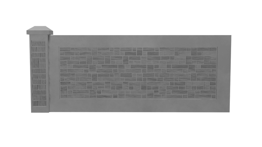
The interactive model could not load. The product reference remains available.
Application cards describe typical use contexts, not automatic suitability. The project team must confirm geometry, loading, exposure, standards and interfaces for the actual location.
Coordinate the product with adjoining construction, access, drainage, safety and the approved project details.
Coordinate the product with adjoining construction, access, drainage, safety and the approved project details.
Coordinate the product with adjoining construction, access, drainage, safety and the approved project details.
Coordinate the product with adjoining construction, access, drainage, safety and the approved project details.
Coordinate the product with adjoining construction, access, drainage, safety and the approved project details.
Coordinate the product with adjoining construction, access, drainage, safety and the approved project details.
These supplied catalogue spreads are shown as references for product understanding. Click any panel to inspect it at full size. Approved project drawings remain the controlling documents.
The Standard Walling System uses repeated posts and panels to replace extensive site masonry and plastering. It is best suited to long, regular boundary runs where survey, footing accuracy and a clear bay schedule allow efficient manufacture and erection. The six inputs alongside form a practical pre-production checklist.
Record the requirement on the current approved drawing or schedule and coordinate it with affected disciplines.
Record the requirement on the current approved drawing or schedule and coordinate it with affected disciplines.
Record the requirement on the current approved drawing or schedule and coordinate it with affected disciplines.
Record the requirement on the current approved drawing or schedule and coordinate it with affected disciplines.
Record the requirement on the current approved drawing or schedule and coordinate it with affected disciplines.
Record the requirement on the current approved drawing or schedule and coordinate it with affected disciplines.
Precast gains programme certainty when survey, design, production, logistics and erection are treated as one connected workflow rather than separate purchases.
Convert survey and technical inputs into an agreed basis.
Freeze the product geometry, interfaces and required checks.
Complete factory production and documented inspection.
Coordinate safe delivery, lifting, line and level on site.
Close interfaces and retain the required handover records.
Controlled moulds and curing improve repeatability, while site teams concentrate on preparation, lifting, interfaces and safe completion. Final performance still depends on the complete engineered system.
A catalogue-backed characteristic to evaluate against the project programme, design basis and installation method.
A catalogue-backed characteristic to evaluate against the project programme, design basis and installation method.
A catalogue-backed characteristic to evaluate against the project programme, design basis and installation method.
A catalogue-backed characteristic to evaluate against the project programme, design basis and installation method.
Twelve practical questions covering selection, engineering, production, handling, installation and documentation.
Long, regular boundaries with repeatable bays, clear access and consistent ground conditions offer the greatest programme advantage.
Available patterns depend on the mould and confirmed system. Use approved samples or catalogue references for visible finishes.
Gate posts, foundations, hinges, clear openings and vehicle loads should be designed separately and coordinated with adjacent wall bays.
Yes, through an engineered stepped arrangement or approved transition details based on surveyed levels.
Project-specific dimensions and interfaces can be reviewed before manufacture, subject to engineering, mould and production feasibility.
Share the latest drawings, quantities, application, levels, loading or hydraulic inputs, site location and required programme.
Yes. The GLB and catalogue explain the product; they do not replace the consultant-approved structural, geotechnical, hydraulic or electrical design.
Yes, after the unit schedule and technical scope are frozen, manufacture and dispatch can be coordinated to the agreed workfront sequence.
Use only approved lifting points, unit weights, equipment and method statements. Stable dunnage, stack height and ground conditions must be planned.
Applicable drawings, material records and inspection documentation can be discussed for the confirmed product and project scope.
Existing levels, dimensions, utilities and tolerances must be surveyed and incorporated into the approved interface details before manufacture.
No. The interactive model is for product understanding. Only the latest approved production and project drawings govern manufacture and installation.
Share the drawings, quantities, site, loading or hydraulic inputs and programme for a product-specific technical discussion.